Reading a multistage pump curve can be a confusing proposition, but the experts at BFS Industries are here to take some of the confusion away. There are seven key things you need to look at when reading a pump curve.
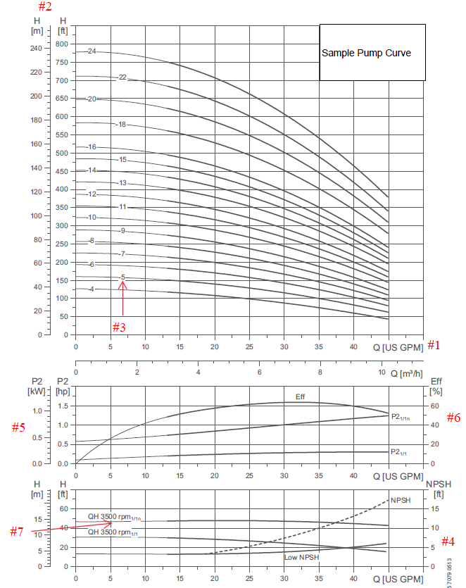
We’ll use the sample pump curve chart below as our example. It represents a typical pump curve for a pump that’s used as a boiler feed pump or condensate pump.

Step 1: Consider Pump Flow
One of the most important things to consider is pump flow. The pump flow is shown in GPM across the X axis. Most pumps sold to American markets will have the flow listed in GPM, but you may see it listed as m3/hr, as well. In this example, the usable part of the pump curve ranges from 1318 GPM to 45 GPM. Selecting a pump located in the middle of that flow rate would be ideal. Oftentimes the preferred pumping range will be shaded darker than the rest of the pump curve.
Step 2: Convert Pump Pressure
The second key thing to notice is what pressure the pump is capable of generating. This is represented in [ft] or [m] TDH (total dynamic head) on the Y axis. So, what is [ft] TDH? Required pump discharge pressure is commonly listed in terms of PSIG, but we can convert PSIG to [ft] TDH using a simple formula. ft TDH=(PSIG x 2.31)/(Specific Gravity)
Water at 212 °F or less has a specific gravity of 1.0. Use this value for feed water tanks that are vented to atmosphere. As water continues to be heated the specific gravity drops. Deaerators typically operate at 5 PSIG 227 °F, which corresponds to a specific gravity of .952.
Step 3: Number Pump Stages
The pump stages will be shown as a number located along the line of each individual pump curve. The more stages you have, the more pressure the pump will generate.
Step 4: Determine NPSH
Each pump has a Net Positive Suction Head (NPSH) required curve based on the pump flow rate. The higher the pump flow rate, the higher the NPSH required will be. For this particular pump, at a 25 GPM flow rate, the pump requires around 3.5’ of NPSH. NPSH available can be calculated based on differential height between water source and pump suction, pipe loss between source and pump suction, and water temperature. There must be more NPSH available than NPSH required for the pump to operate properly.
Step 5: Calculate Horsepower Required
You can calculate horsepower required manually using the values found in this section, but most pump manufacturers will just have motor sizes listed next to their standard pump offerings. In this example, P21/1n represents HP per Low NPSH stage. Each pump only has one low NPSH stage, and P21/1 represents HP per standard stage. If we take the 11-stage curve as an example, we can calculate the HP required as follows:
HP Required=(1 x low NPSH stage) x 1.25 + ( 10 x regular stages) x .3 = 4.25 HP Required
We like to select the max HP required per stage across the entire curve so that we select a motor that is not overloaded at any point across the pump’s operating range.
Step 6: Find Pump Efficiency
Pump efficiency is shown as a percentage and is graphed based on the pump flow rate. In the middle of the flow rate range, the efficiency is going to be highest, with the efficiency dropping off at either end of the curve. For example, this pump has an efficiency of 62% at 32 GPM but an efficiency of 50% at 15 GPM.
Step 7: Figure Pump Revolutions Per Minute (RPM)
Somewhere on the pump curve, the manufacturer will list what speed the pump is designed to rotate. A standard 60 hz 2-pole electric motor will rotate at 3,500 RPM (nominal rating). This is what you will find used on many common centrifugal pumps used for boiler feed applications. Other motor options would be 60 hz 4-pole motors, which rotate at 1750 RPM. Or, if overseas, 50 hz 2-pole motors rotate at 2900 RPM.
Contact BFS Industries for a quote on all your pumping needs. We have experts here to help you determine what is the best fit for your application.

